In the final blog post I wanted to present a demo of our project that we recorded one day before the final presentation.
This week, during our final workshop, we presented this demo to researchers from BIG Group who run the "Interactive Devices" unit at the University of Bristol. We answered their questions about our project and we hope that we left them with a good impression.
We are also finishing the work on the final report that will be the assessed together with this blog and the demo.
Sunday, 14 December 2014

Sunday, 7 December 2014
Scenarios
In this blog post I wanted to present some finished example use cases that mainly Dominique and Derek designed while the rest of us carried out work on the rendering. We added the scenarios to our software so that it is nearly ready for the demo. We didn't manage to automatically detect the action of folding the paper and for that reason we manually change the images that are to be displayed on the paper, however the projection automatically resizes to to match the piece of paper presented. So here are the scenarios:
Book
This was one of our ideas that reaches back to the brainstorming. We thought it would be very natural to use in the future a real-paper-like display that could be a kindle device. By folding we could open and close the book, by turning the paper around, we could see the back and front cover or make bookmarks by folding a corner of the paper. Also, by unfolding the paper to make it bigger than standard book size, we could implement an action of fetching additional content from the Internet about the book, or display a dictionary with definitions of words etc.


Shopping basket
Another idea was to fold an origami of a house and display a website of an online shop. We could swipe to browse products and add them to our basket.


The Game
We also thought an interactive origami could be used for entertainment and we proposed a simple to fold origami that could be used as "Hungry hippos" game. This old commercial presents the concept of the game rather well:
Rather than using the special, single purpose device for such a game, we could fold our interactive paper and allow people to play the game by tapping the four folded corners:


Foldable mobile phone
My favourite example on how we could use shape changing display is a foldable mobile device that can be unfolded into a tabled and provide bigger display area. We were thinking of using the device as mobile phone when folded into a 5' piece of paper, that can be expanded into a much bigger surface if we required more details. We presented applications of map and web browsing that would response to the change of the display and show more content to the user.


Book
This was one of our ideas that reaches back to the brainstorming. We thought it would be very natural to use in the future a real-paper-like display that could be a kindle device. By folding we could open and close the book, by turning the paper around, we could see the back and front cover or make bookmarks by folding a corner of the paper. Also, by unfolding the paper to make it bigger than standard book size, we could implement an action of fetching additional content from the Internet about the book, or display a dictionary with definitions of words etc.
Shopping basket
Another idea was to fold an origami of a house and display a website of an online shop. We could swipe to browse products and add them to our basket.
By flipping the origami of the house upside down, it would resemble the shape of a basket, displaying what items we added to it so far. Once ready for the checkout, the device could take accept wireless payment.
The Game
We also thought an interactive origami could be used for entertainment and we proposed a simple to fold origami that could be used as "Hungry hippos" game. This old commercial presents the concept of the game rather well:
Rather than using the special, single purpose device for such a game, we could fold our interactive paper and allow people to play the game by tapping the four folded corners:
Foldable mobile phone
My favourite example on how we could use shape changing display is a foldable mobile device that can be unfolded into a tabled and provide bigger display area. We were thinking of using the device as mobile phone when folded into a 5' piece of paper, that can be expanded into a much bigger surface if we required more details. We presented applications of map and web browsing that would response to the change of the display and show more content to the user.
Friday, 5 December 2014
Texturing
This week we were still "fighting" with the triangles and rendering in OpenGL using MOgre (.NET version of Ogre 3D SDK). However, the victory was ours. We managed to display a textured rectangle with a cover of the book.
As mentioned in my previous entry, a recangle can be displayed using a graphics library such as OpenGL as a list of triangles. Defining triangles for us is still an issue. Sometimes our rectangles would be "filipped" if we specify at least one vertex in wrong order. We tried to mitigate this by "sorting" our points based on stack overflow answers to similar issue. However we didn't succeed. The temporary solution was to tell the graphics card explicity to draw all faces of triangles, so even if triangles were fliped, they would be still drawn. Graphics cards by default don't draw back faces of the mesh so half of our rectangle could appear to be missing.
Texturing on the other hand uses yet different coordinate systems. Given a texture, we have to specify 2-D coordinates that map on the mesh, using only values between 0 and 1. Point (0,0) is top left corner of the mesh and (1,1) is bottom right. So we need to take our 4 or 6 vertices of the ractangle and map texture to them. That gave us a bit of a headache.
However this week we were in most cases able to display a textured rectangle as seen on the picture below:
With the recangle sometimes displaying as "half flipped", texturing would also suffer from that issue. Sometimes as we move the paper around, half of the book cover would be inverted or mirrored. That means we still need to fix sorting 3-D points clockwise.
With the weekend ahead of us and the demo day coming in just 4 days, we need to find a way to change between different scenarios we prepared and to fix the sorting issue before we are ready for the presentation.
As mentioned in my previous entry, a recangle can be displayed using a graphics library such as OpenGL as a list of triangles. Defining triangles for us is still an issue. Sometimes our rectangles would be "filipped" if we specify at least one vertex in wrong order. We tried to mitigate this by "sorting" our points based on stack overflow answers to similar issue. However we didn't succeed. The temporary solution was to tell the graphics card explicity to draw all faces of triangles, so even if triangles were fliped, they would be still drawn. Graphics cards by default don't draw back faces of the mesh so half of our rectangle could appear to be missing.
Texturing on the other hand uses yet different coordinate systems. Given a texture, we have to specify 2-D coordinates that map on the mesh, using only values between 0 and 1. Point (0,0) is top left corner of the mesh and (1,1) is bottom right. So we need to take our 4 or 6 vertices of the ractangle and map texture to them. That gave us a bit of a headache.
However this week we were in most cases able to display a textured rectangle as seen on the picture below:
 |
| Textured rectangle projected on top of the paper |
With the recangle sometimes displaying as "half flipped", texturing would also suffer from that issue. Sometimes as we move the paper around, half of the book cover would be inverted or mirrored. That means we still need to fix sorting 3-D points clockwise.
With the weekend ahead of us and the demo day coming in just 4 days, we need to find a way to change between different scenarios we prepared and to fix the sorting issue before we are ready for the presentation.
Sunday, 30 November 2014
Tracking paper
Having the calibration done last week, in week 4 we moved on to work on tracking the paper using Kinect and trying to project something onto the detected location.
To make things simple to start with, we just wanted to display a solid colour rectangle on top of the piece of paper. These are the steps we followed in order to achieve this:
Detecting the paper
This task was fairly straight forward. We use OpenCV methods of findContour in order to find points around the shape of the paper in the colour image from Kinect sensor. Having a vast collection of points was not necessarily handy, so we simplified the contour using an approximation method provided by OpenCV, approxPolyDP.
Finding 3-D coordinates
The image we received in previous step only gives us a few points and their X and Y coordinates on the camera image. Now we had to correlate these points with the depth map provided by the Kinect in order to find which depth values correspond to a given (X, Y) pair. Thanks to this mapping (again provided out-of-box by the Kinect SDK) we obtained 3-D coordinates (X, Y, Z) for every corner of the paper detected.
Translating to Ogre space
The 3-d point we obtained was still relating to what the camera and depth sensors "saw". We had to again apply Transform matrix from Ogre to our points in order to convert these coordinates to Ogre space.
Drawing the quad
Now having a set of 4 points (in case of rectangular shape) we needed to draw a quad in Ogre. This task proved the most difficult to me. In OpenCV drawing a rectangle is straightforward, just select point, width, height and done, easy.
Not in 3-D world.
I never had too much experience with 3D engines and I found it difficult to think in terms of triangles. Everything has to be a triangle. Not only that! Ogre draws everything in anti-clockwise order around the origin, if this order is not correct, rendering goes wrong.
To make things even more complicated, there are three modes of drawing triangles (illustrated below):
This week we were only able to draw a quad and translate it to the position detected, which is not yet exactly what we are aiming for, because that way we couldn't resize or rotate the quad if the paper orientation changes, but we hope to finish the projection early next week. The video below demonstrates what we implemented:
To make things simple to start with, we just wanted to display a solid colour rectangle on top of the piece of paper. These are the steps we followed in order to achieve this:
Detecting the paper
This task was fairly straight forward. We use OpenCV methods of findContour in order to find points around the shape of the paper in the colour image from Kinect sensor. Having a vast collection of points was not necessarily handy, so we simplified the contour using an approximation method provided by OpenCV, approxPolyDP.
Finding 3-D coordinates
The image we received in previous step only gives us a few points and their X and Y coordinates on the camera image. Now we had to correlate these points with the depth map provided by the Kinect in order to find which depth values correspond to a given (X, Y) pair. Thanks to this mapping (again provided out-of-box by the Kinect SDK) we obtained 3-D coordinates (X, Y, Z) for every corner of the paper detected.
Translating to Ogre space
The 3-d point we obtained was still relating to what the camera and depth sensors "saw". We had to again apply Transform matrix from Ogre to our points in order to convert these coordinates to Ogre space.
Drawing the quad
Now having a set of 4 points (in case of rectangular shape) we needed to draw a quad in Ogre. This task proved the most difficult to me. In OpenCV drawing a rectangle is straightforward, just select point, width, height and done, easy.
Not in 3-D world.
I never had too much experience with 3D engines and I found it difficult to think in terms of triangles. Everything has to be a triangle. Not only that! Ogre draws everything in anti-clockwise order around the origin, if this order is not correct, rendering goes wrong.
To make things even more complicated, there are three modes of drawing triangles (illustrated below):
- triangle list - where every triangle point is specified explicitly
- triangle stripe - where first triangle points need to be specified, and then every additional points creates new triangle
- triangle fan - where central point is selected and further points draw triangles around that point
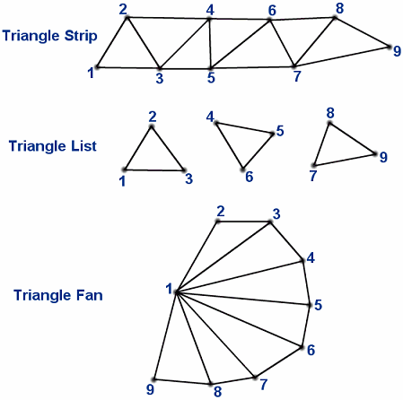 |
| Image taken from http://www.vrarchitect.net/anu/cg/surfaceModeling/polygonMesh.en.html |
This week we were only able to draw a quad and translate it to the position detected, which is not yet exactly what we are aiming for, because that way we couldn't resize or rotate the quad if the paper orientation changes, but we hope to finish the projection early next week. The video below demonstrates what we implemented:
Sunday, 23 November 2014
Calibration success
In the third week of our work on the implementation of the idea we finally got the calibration part of the project working.
I have to say that I struggled with the calibration, and majority the code that we created in past two weeks is now not going to be used. Thanks to Florian and Diego, two of the lab assistants from BIG lab, we finally got the calibration done. They gave us their piece of software that they used in some of their project in BIG lab. Using their software we finally got the values for OpenGL matrices that we could apply to Ogre.
The software displays a chessboard of given size on a secondary display, which in our case is the projector. The Kinect colour camera and depth sensor stream values constantly. When chessboard corners are detected, the software compares the projected chessboard image with observed image. We take 6 images at different distances and angles. The program also computes a root mean square error of the re projection, which we were advised should be less than two.
Once we have the parameters of the camera calculated, we can apply the projection values into a 3D graphics engine and be able to display "corrected" images onto a piece of paper.
When reflecting upon this week, on one hand I am mad at myself that we spend almost two weeks on something that we then decided to ditch in the end, but on the other hand the benefit is that I learned a lot about camera calibration.
I have to say that I struggled with the calibration, and majority the code that we created in past two weeks is now not going to be used. Thanks to Florian and Diego, two of the lab assistants from BIG lab, we finally got the calibration done. They gave us their piece of software that they used in some of their project in BIG lab. Using their software we finally got the values for OpenGL matrices that we could apply to Ogre.
 |
| Florian's calibration software |
The software displays a chessboard of given size on a secondary display, which in our case is the projector. The Kinect colour camera and depth sensor stream values constantly. When chessboard corners are detected, the software compares the projected chessboard image with observed image. We take 6 images at different distances and angles. The program also computes a root mean square error of the re projection, which we were advised should be less than two.
 |
| Reprojection view |
When reflecting upon this week, on one hand I am mad at myself that we spend almost two weeks on something that we then decided to ditch in the end, but on the other hand the benefit is that I learned a lot about camera calibration.
Saturday, 15 November 2014
Second week of the implementation
This week me and Andres and Adam, we tried to calibrate the Kinect with the projector using the chessboard method.
We got the code working for drawing a chessboard, as well as OpenCV code for detecting contours of the shape to find where chessboard is, however we then found that OpenCV has already got a special method "findChessboard".
In order to help ourselves to understand in depth how calibration works, we did more research and found papers and other projects on this topic:
We got the code working for drawing a chessboard, as well as OpenCV code for detecting contours of the shape to find where chessboard is, however we then found that OpenCV has already got a special method "findChessboard".
In order to help ourselves to understand in depth how calibration works, we did more research and found papers and other projects on this topic:
- https://github.com/genekogan/KinectProjectorToolkit
- Kinect/projector calibration project - I couldn't run it on my machine, however we analysed the source code to understand how OpenCV is used for calibration.
- https://github.com/Kj1/ofxProjectorKinectCalibration
- Calibration project, again I couldn't run it on our machine, mostly due to lots of dependencies on Openframeworks library, however the code again helped us to understand what exactly we need to do in practice.
- Demo:
MCBTH Kinect-projector calibration from Hangaar.net on Vimeo.
The second half of the team spend time on getting to know the Ogre graphics engine. Once we would be ready with the calibration and obtained a "view matrix" parameters and a "projection matrix" parameters, based on extrinsic and intrinsics parameters of the camera, we could apply those two matrices to the images rendered in OpenGL so that the transformed images looks good when projected onto a surface.
Sunday, 9 November 2014
Start of work
This week we finally started implementing our idea. We received the equipment we requested for the project:

- Kinect Sensor - for tracking the paper in 3D space
- Projector - for displaying images onto the surface
- Laptop - with development tools ready to go
- Tripod - to be able to keep the Kinect and the camera above the working surface
During the lab we split into two sub teams. Me and Andres we decided to focus on figuring how to calibrate the camera and the depth sensor with our projector.
Adam, Derek and Dominique spend the time in the lab to fix the sensor on top of the projector using the tripod. And this was their final work:
Adam, Derek and Dominique spend the time in the lab to fix the sensor on top of the projector using the tripod. And this was their final work:
So what about the projector calibration?
If we just use the Kinect with camera, we wouldn't be able to project accurate images onto the surface which is at the angle. In order to fix any distortions of the projection and to be able to project something in a specified region (the paper we track using Kinect colour camera) we needed to know the correspondence between the images projected and those captured by the camera.
A standard way of doing this is to display a known "chess board" images - known in terms of number of black and white squares and their sizes. Then using the camera we try to detect the corners of the chessboard and compare the result to what we know about the chessboard. This way we can calculate the extrinsic and intrinsic parameters of the camera and apply necessary transformation to the image that goes to the projector, so that the final result is "undistorted".
There are documented ways of calibrating the camera on OpenCV website. However, the Kinect also has got a depth sensor. Lab assistants pointed out that the calibration process needs to take into account the depth values read from the Kinect in order to change the project if we for example lift the paper, as z-coordinates would then change and the we would want to scale the projected image. Florian, on of the lab assistants, pointed us to an open source project that extends standard OpenCV calibration process with making use of the depth values from Kinect. The project can be found here.
If we just use the Kinect with camera, we wouldn't be able to project accurate images onto the surface which is at the angle. In order to fix any distortions of the projection and to be able to project something in a specified region (the paper we track using Kinect colour camera) we needed to know the correspondence between the images projected and those captured by the camera.
A standard way of doing this is to display a known "chess board" images - known in terms of number of black and white squares and their sizes. Then using the camera we try to detect the corners of the chessboard and compare the result to what we know about the chessboard. This way we can calculate the extrinsic and intrinsic parameters of the camera and apply necessary transformation to the image that goes to the projector, so that the final result is "undistorted".
There are documented ways of calibrating the camera on OpenCV website. However, the Kinect also has got a depth sensor. Lab assistants pointed out that the calibration process needs to take into account the depth values read from the Kinect in order to change the project if we for example lift the paper, as z-coordinates would then change and the we would want to scale the projected image. Florian, on of the lab assistants, pointed us to an open source project that extends standard OpenCV calibration process with making use of the depth values from Kinect. The project can be found here.
We set up a project in C# to use Kinect SDK and we wanted to spend the rest of the week translating the C++ code from the website into C#, using Emgu CV - a .NET wrapper for OpenCV.
Subscribe to:
Posts (Atom)