In the final blog post I wanted to present a demo of our project that we recorded one day before the final presentation.
This week, during our final workshop, we presented this demo to researchers from BIG Group who run the "Interactive Devices" unit at the University of Bristol. We answered their questions about our project and we hope that we left them with a good impression.
We are also finishing the work on the final report that will be the assessed together with this blog and the demo.
Sunday, 14 December 2014

Sunday, 7 December 2014
Scenarios
In this blog post I wanted to present some finished example use cases that mainly Dominique and Derek designed while the rest of us carried out work on the rendering. We added the scenarios to our software so that it is nearly ready for the demo. We didn't manage to automatically detect the action of folding the paper and for that reason we manually change the images that are to be displayed on the paper, however the projection automatically resizes to to match the piece of paper presented. So here are the scenarios:
Book
This was one of our ideas that reaches back to the brainstorming. We thought it would be very natural to use in the future a real-paper-like display that could be a kindle device. By folding we could open and close the book, by turning the paper around, we could see the back and front cover or make bookmarks by folding a corner of the paper. Also, by unfolding the paper to make it bigger than standard book size, we could implement an action of fetching additional content from the Internet about the book, or display a dictionary with definitions of words etc.


Shopping basket
Another idea was to fold an origami of a house and display a website of an online shop. We could swipe to browse products and add them to our basket.


The Game
We also thought an interactive origami could be used for entertainment and we proposed a simple to fold origami that could be used as "Hungry hippos" game. This old commercial presents the concept of the game rather well:
Rather than using the special, single purpose device for such a game, we could fold our interactive paper and allow people to play the game by tapping the four folded corners:


Foldable mobile phone
My favourite example on how we could use shape changing display is a foldable mobile device that can be unfolded into a tabled and provide bigger display area. We were thinking of using the device as mobile phone when folded into a 5' piece of paper, that can be expanded into a much bigger surface if we required more details. We presented applications of map and web browsing that would response to the change of the display and show more content to the user.


Book
This was one of our ideas that reaches back to the brainstorming. We thought it would be very natural to use in the future a real-paper-like display that could be a kindle device. By folding we could open and close the book, by turning the paper around, we could see the back and front cover or make bookmarks by folding a corner of the paper. Also, by unfolding the paper to make it bigger than standard book size, we could implement an action of fetching additional content from the Internet about the book, or display a dictionary with definitions of words etc.
Shopping basket
Another idea was to fold an origami of a house and display a website of an online shop. We could swipe to browse products and add them to our basket.
By flipping the origami of the house upside down, it would resemble the shape of a basket, displaying what items we added to it so far. Once ready for the checkout, the device could take accept wireless payment.
The Game
We also thought an interactive origami could be used for entertainment and we proposed a simple to fold origami that could be used as "Hungry hippos" game. This old commercial presents the concept of the game rather well:
Rather than using the special, single purpose device for such a game, we could fold our interactive paper and allow people to play the game by tapping the four folded corners:
Foldable mobile phone
My favourite example on how we could use shape changing display is a foldable mobile device that can be unfolded into a tabled and provide bigger display area. We were thinking of using the device as mobile phone when folded into a 5' piece of paper, that can be expanded into a much bigger surface if we required more details. We presented applications of map and web browsing that would response to the change of the display and show more content to the user.
Friday, 5 December 2014
Texturing
This week we were still "fighting" with the triangles and rendering in OpenGL using MOgre (.NET version of Ogre 3D SDK). However, the victory was ours. We managed to display a textured rectangle with a cover of the book.
As mentioned in my previous entry, a recangle can be displayed using a graphics library such as OpenGL as a list of triangles. Defining triangles for us is still an issue. Sometimes our rectangles would be "filipped" if we specify at least one vertex in wrong order. We tried to mitigate this by "sorting" our points based on stack overflow answers to similar issue. However we didn't succeed. The temporary solution was to tell the graphics card explicity to draw all faces of triangles, so even if triangles were fliped, they would be still drawn. Graphics cards by default don't draw back faces of the mesh so half of our rectangle could appear to be missing.
Texturing on the other hand uses yet different coordinate systems. Given a texture, we have to specify 2-D coordinates that map on the mesh, using only values between 0 and 1. Point (0,0) is top left corner of the mesh and (1,1) is bottom right. So we need to take our 4 or 6 vertices of the ractangle and map texture to them. That gave us a bit of a headache.
However this week we were in most cases able to display a textured rectangle as seen on the picture below:
With the recangle sometimes displaying as "half flipped", texturing would also suffer from that issue. Sometimes as we move the paper around, half of the book cover would be inverted or mirrored. That means we still need to fix sorting 3-D points clockwise.
With the weekend ahead of us and the demo day coming in just 4 days, we need to find a way to change between different scenarios we prepared and to fix the sorting issue before we are ready for the presentation.
As mentioned in my previous entry, a recangle can be displayed using a graphics library such as OpenGL as a list of triangles. Defining triangles for us is still an issue. Sometimes our rectangles would be "filipped" if we specify at least one vertex in wrong order. We tried to mitigate this by "sorting" our points based on stack overflow answers to similar issue. However we didn't succeed. The temporary solution was to tell the graphics card explicity to draw all faces of triangles, so even if triangles were fliped, they would be still drawn. Graphics cards by default don't draw back faces of the mesh so half of our rectangle could appear to be missing.
Texturing on the other hand uses yet different coordinate systems. Given a texture, we have to specify 2-D coordinates that map on the mesh, using only values between 0 and 1. Point (0,0) is top left corner of the mesh and (1,1) is bottom right. So we need to take our 4 or 6 vertices of the ractangle and map texture to them. That gave us a bit of a headache.
However this week we were in most cases able to display a textured rectangle as seen on the picture below:
 |
| Textured rectangle projected on top of the paper |
With the recangle sometimes displaying as "half flipped", texturing would also suffer from that issue. Sometimes as we move the paper around, half of the book cover would be inverted or mirrored. That means we still need to fix sorting 3-D points clockwise.
With the weekend ahead of us and the demo day coming in just 4 days, we need to find a way to change between different scenarios we prepared and to fix the sorting issue before we are ready for the presentation.
Sunday, 30 November 2014
Tracking paper
Having the calibration done last week, in week 4 we moved on to work on tracking the paper using Kinect and trying to project something onto the detected location.
To make things simple to start with, we just wanted to display a solid colour rectangle on top of the piece of paper. These are the steps we followed in order to achieve this:
Detecting the paper
This task was fairly straight forward. We use OpenCV methods of findContour in order to find points around the shape of the paper in the colour image from Kinect sensor. Having a vast collection of points was not necessarily handy, so we simplified the contour using an approximation method provided by OpenCV, approxPolyDP.
Finding 3-D coordinates
The image we received in previous step only gives us a few points and their X and Y coordinates on the camera image. Now we had to correlate these points with the depth map provided by the Kinect in order to find which depth values correspond to a given (X, Y) pair. Thanks to this mapping (again provided out-of-box by the Kinect SDK) we obtained 3-D coordinates (X, Y, Z) for every corner of the paper detected.
Translating to Ogre space
The 3-d point we obtained was still relating to what the camera and depth sensors "saw". We had to again apply Transform matrix from Ogre to our points in order to convert these coordinates to Ogre space.
Drawing the quad
Now having a set of 4 points (in case of rectangular shape) we needed to draw a quad in Ogre. This task proved the most difficult to me. In OpenCV drawing a rectangle is straightforward, just select point, width, height and done, easy.
Not in 3-D world.
I never had too much experience with 3D engines and I found it difficult to think in terms of triangles. Everything has to be a triangle. Not only that! Ogre draws everything in anti-clockwise order around the origin, if this order is not correct, rendering goes wrong.
To make things even more complicated, there are three modes of drawing triangles (illustrated below):
This week we were only able to draw a quad and translate it to the position detected, which is not yet exactly what we are aiming for, because that way we couldn't resize or rotate the quad if the paper orientation changes, but we hope to finish the projection early next week. The video below demonstrates what we implemented:
To make things simple to start with, we just wanted to display a solid colour rectangle on top of the piece of paper. These are the steps we followed in order to achieve this:
Detecting the paper
This task was fairly straight forward. We use OpenCV methods of findContour in order to find points around the shape of the paper in the colour image from Kinect sensor. Having a vast collection of points was not necessarily handy, so we simplified the contour using an approximation method provided by OpenCV, approxPolyDP.
Finding 3-D coordinates
The image we received in previous step only gives us a few points and their X and Y coordinates on the camera image. Now we had to correlate these points with the depth map provided by the Kinect in order to find which depth values correspond to a given (X, Y) pair. Thanks to this mapping (again provided out-of-box by the Kinect SDK) we obtained 3-D coordinates (X, Y, Z) for every corner of the paper detected.
Translating to Ogre space
The 3-d point we obtained was still relating to what the camera and depth sensors "saw". We had to again apply Transform matrix from Ogre to our points in order to convert these coordinates to Ogre space.
Drawing the quad
Now having a set of 4 points (in case of rectangular shape) we needed to draw a quad in Ogre. This task proved the most difficult to me. In OpenCV drawing a rectangle is straightforward, just select point, width, height and done, easy.
Not in 3-D world.
I never had too much experience with 3D engines and I found it difficult to think in terms of triangles. Everything has to be a triangle. Not only that! Ogre draws everything in anti-clockwise order around the origin, if this order is not correct, rendering goes wrong.
To make things even more complicated, there are three modes of drawing triangles (illustrated below):
- triangle list - where every triangle point is specified explicitly
- triangle stripe - where first triangle points need to be specified, and then every additional points creates new triangle
- triangle fan - where central point is selected and further points draw triangles around that point
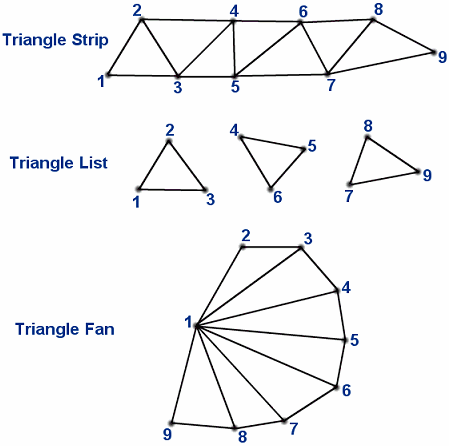 |
| Image taken from http://www.vrarchitect.net/anu/cg/surfaceModeling/polygonMesh.en.html |
This week we were only able to draw a quad and translate it to the position detected, which is not yet exactly what we are aiming for, because that way we couldn't resize or rotate the quad if the paper orientation changes, but we hope to finish the projection early next week. The video below demonstrates what we implemented:
Sunday, 23 November 2014
Calibration success
In the third week of our work on the implementation of the idea we finally got the calibration part of the project working.
I have to say that I struggled with the calibration, and majority the code that we created in past two weeks is now not going to be used. Thanks to Florian and Diego, two of the lab assistants from BIG lab, we finally got the calibration done. They gave us their piece of software that they used in some of their project in BIG lab. Using their software we finally got the values for OpenGL matrices that we could apply to Ogre.
The software displays a chessboard of given size on a secondary display, which in our case is the projector. The Kinect colour camera and depth sensor stream values constantly. When chessboard corners are detected, the software compares the projected chessboard image with observed image. We take 6 images at different distances and angles. The program also computes a root mean square error of the re projection, which we were advised should be less than two.
Once we have the parameters of the camera calculated, we can apply the projection values into a 3D graphics engine and be able to display "corrected" images onto a piece of paper.
When reflecting upon this week, on one hand I am mad at myself that we spend almost two weeks on something that we then decided to ditch in the end, but on the other hand the benefit is that I learned a lot about camera calibration.
I have to say that I struggled with the calibration, and majority the code that we created in past two weeks is now not going to be used. Thanks to Florian and Diego, two of the lab assistants from BIG lab, we finally got the calibration done. They gave us their piece of software that they used in some of their project in BIG lab. Using their software we finally got the values for OpenGL matrices that we could apply to Ogre.
 |
| Florian's calibration software |
The software displays a chessboard of given size on a secondary display, which in our case is the projector. The Kinect colour camera and depth sensor stream values constantly. When chessboard corners are detected, the software compares the projected chessboard image with observed image. We take 6 images at different distances and angles. The program also computes a root mean square error of the re projection, which we were advised should be less than two.
 |
| Reprojection view |
When reflecting upon this week, on one hand I am mad at myself that we spend almost two weeks on something that we then decided to ditch in the end, but on the other hand the benefit is that I learned a lot about camera calibration.
Saturday, 15 November 2014
Second week of the implementation
This week me and Andres and Adam, we tried to calibrate the Kinect with the projector using the chessboard method.
We got the code working for drawing a chessboard, as well as OpenCV code for detecting contours of the shape to find where chessboard is, however we then found that OpenCV has already got a special method "findChessboard".
In order to help ourselves to understand in depth how calibration works, we did more research and found papers and other projects on this topic:
We got the code working for drawing a chessboard, as well as OpenCV code for detecting contours of the shape to find where chessboard is, however we then found that OpenCV has already got a special method "findChessboard".
In order to help ourselves to understand in depth how calibration works, we did more research and found papers and other projects on this topic:
- https://github.com/genekogan/KinectProjectorToolkit
- Kinect/projector calibration project - I couldn't run it on my machine, however we analysed the source code to understand how OpenCV is used for calibration.
- https://github.com/Kj1/ofxProjectorKinectCalibration
- Calibration project, again I couldn't run it on our machine, mostly due to lots of dependencies on Openframeworks library, however the code again helped us to understand what exactly we need to do in practice.
- Demo:
MCBTH Kinect-projector calibration from Hangaar.net on Vimeo.
The second half of the team spend time on getting to know the Ogre graphics engine. Once we would be ready with the calibration and obtained a "view matrix" parameters and a "projection matrix" parameters, based on extrinsic and intrinsics parameters of the camera, we could apply those two matrices to the images rendered in OpenGL so that the transformed images looks good when projected onto a surface.
Sunday, 9 November 2014
Start of work
This week we finally started implementing our idea. We received the equipment we requested for the project:

- Kinect Sensor - for tracking the paper in 3D space
- Projector - for displaying images onto the surface
- Laptop - with development tools ready to go
- Tripod - to be able to keep the Kinect and the camera above the working surface
During the lab we split into two sub teams. Me and Andres we decided to focus on figuring how to calibrate the camera and the depth sensor with our projector.
Adam, Derek and Dominique spend the time in the lab to fix the sensor on top of the projector using the tripod. And this was their final work:
Adam, Derek and Dominique spend the time in the lab to fix the sensor on top of the projector using the tripod. And this was their final work:
So what about the projector calibration?
If we just use the Kinect with camera, we wouldn't be able to project accurate images onto the surface which is at the angle. In order to fix any distortions of the projection and to be able to project something in a specified region (the paper we track using Kinect colour camera) we needed to know the correspondence between the images projected and those captured by the camera.
A standard way of doing this is to display a known "chess board" images - known in terms of number of black and white squares and their sizes. Then using the camera we try to detect the corners of the chessboard and compare the result to what we know about the chessboard. This way we can calculate the extrinsic and intrinsic parameters of the camera and apply necessary transformation to the image that goes to the projector, so that the final result is "undistorted".
There are documented ways of calibrating the camera on OpenCV website. However, the Kinect also has got a depth sensor. Lab assistants pointed out that the calibration process needs to take into account the depth values read from the Kinect in order to change the project if we for example lift the paper, as z-coordinates would then change and the we would want to scale the projected image. Florian, on of the lab assistants, pointed us to an open source project that extends standard OpenCV calibration process with making use of the depth values from Kinect. The project can be found here.
If we just use the Kinect with camera, we wouldn't be able to project accurate images onto the surface which is at the angle. In order to fix any distortions of the projection and to be able to project something in a specified region (the paper we track using Kinect colour camera) we needed to know the correspondence between the images projected and those captured by the camera.
A standard way of doing this is to display a known "chess board" images - known in terms of number of black and white squares and their sizes. Then using the camera we try to detect the corners of the chessboard and compare the result to what we know about the chessboard. This way we can calculate the extrinsic and intrinsic parameters of the camera and apply necessary transformation to the image that goes to the projector, so that the final result is "undistorted".
There are documented ways of calibrating the camera on OpenCV website. However, the Kinect also has got a depth sensor. Lab assistants pointed out that the calibration process needs to take into account the depth values read from the Kinect in order to change the project if we for example lift the paper, as z-coordinates would then change and the we would want to scale the projected image. Florian, on of the lab assistants, pointed us to an open source project that extends standard OpenCV calibration process with making use of the depth values from Kinect. The project can be found here.
We set up a project in C# to use Kinect SDK and we wanted to spend the rest of the week translating the C++ code from the website into C#, using Emgu CV - a .NET wrapper for OpenCV.
Saturday, 8 November 2014
Final idea - Projectagami
After this the lab session this week, a lot of discussion and huge help from our lovely lab assistants, we can finally say that we have got our final idea!
The code-name for our project is "Projectagami". We are inspired by the idea of flexible surfaces and displays. I was personally very impressed when I saw this video from Microsoft Research:
This project uses a flexible sensor to change what is displayed on a LCD display. Our team on the other hand wanted explore how we can interact with fold-able surfaces such as paper. Rather than having a fixed display, we would like to be able to project images onto folded paper. This is why we called our project "Projectagami" - we want to combine projections with the idea of origami and create a tangible interface.
Below is the list of papers we researched that that are discussing topics of foldable surfaces and origami interactions:
The code-name for our project is "Projectagami". We are inspired by the idea of flexible surfaces and displays. I was personally very impressed when I saw this video from Microsoft Research:
This project uses a flexible sensor to change what is displayed on a LCD display. Our team on the other hand wanted explore how we can interact with fold-able surfaces such as paper. Rather than having a fixed display, we would like to be able to project images onto folded paper. This is why we called our project "Projectagami" - we want to combine projections with the idea of origami and create a tangible interface.
Below is the list of papers we researched that that are discussing topics of foldable surfaces and origami interactions:
Year + Title + Link
|
Summary/ Interesting Findings/ Implications for our project
|
[2013] Flexpad: Highly Flexible Bending Interactions
for Projected Handheld Displays , LINK
|
Projects onto a flexible surface using Kinect (depth camera) and a projector. They are able to detect and analyse deformations in the surface in real-time thereby allowing them to project an adjusted image also in real-time. They present an algorithm that can be used to capture complex deformations in high detail and in real-time. This could be useful for our project.
|
[2013] Novel User Interaction Styles with Flexible / Rollable
Screens, LINK
|
Gathers feedback around flexible screens and potential technologies to use for implementation. No actual implementation.
Device uses a rollable display - they do not use a projector.
Has multiple modes and changes UI according to the mode it is in.
|
[2012] PyzoFlex: Printed Piezoelectric Pressure Sensing Foil, LINK
|
Used Piezoelectric pressure sensors in the form of a matrix to detect pressure and temperature. It is different to previous touch sensing that uses capacitive and resistive surfaces because it is able to ‘easily’ detect pressure.
|
[2014] FlexSense: A Transparent Self-Sensing Deformable Surface, LINK
|
This paper develops on earlier research on piezoelectric sensing (above). Using machine learning, they are able to detect the shape of the deformed surface.
Applications described: transparent smart cover for tablets, external high-DoF (Degrees of Freedom) input device
|
FoldMe: Interacting with Double-sided Foldable Displays, LINK
|
Authors investigated the idea of a foldable display that folds similar to a book (i.e. open, close, fold round to back, lay flat)
|
Estimation of Folding Operation
Using Silhouette of Origami
|
Paper for recognising fold operations in origami
|
Sunday, 2 November 2014
Literature review
This week we had further brain-storming sessions as we seem not quite yet to agree on the final idea. We want to be able to finally settle on one particular concept during next week's workshop.
Here is the summary of literature review for the ideas we researched so far:
Here is the summary of literature review for the ideas we researched so far:
Year + Title + Link + Initial
|
Summary/ Interesting Findings/ Implications for our project
|
KITTY glove using Bluetooth, that is similar to what we want to do: and removes the need to type on a specific pressure sensitive surface. To detect letters (QWERTY layout) they use specific contact point Presents the use case of virtual/ augmented reality (e.g. typing while wearing Oculus Rift).
Updated version is a little less intrusive, but we could potentially make finger socks instead of gloves which could be less intrusive? Users commented on haptic feedback- perhaps we could use vibrations/sound when a letter is registered? Unpractised users took 2-7 secs per letter, perhaps we could improve on this with sensors or parallelisation: users wanted a tutorial
| |
[2009] Fast Finger Tracking System for In-air
|
Markerless tracking of finger movements from a camera, recognising typing on air. To achieve typing in real time, hardware that parallelizes image processing (throughput 138 fps)
(Ideally we’d want markered tracking so that the system could be used on a users lap)
|
A universal input device for both text (Korean) and Braille input was developed in a Glove-typed interface using all the joints of the four fingers and thumbs of both hands. Korean characters showed comparable performance with cellular phone input keypads, but inferior to conventional keyboard. Letters are typed by the touching of certain finger combinations (not QWERTY).
| |
PointGrab
|
This is not really a paper, but I wanted to investigate if someone had already tried to develop a system for home automation using gesture tracking. It turns out that there is a company called PointGrab that has been doing it for a few years. Here is the website: http://www.pointgrab.com/
|
Dextype
|
Dextype is a product that lets you type in the air. Because typing in air is so inaccurate, dextype helps by trying to figure out the key that you pressed. Also, it includes functions that make it very easy to complete words, draw symbols in air and correct previous typed input. Here is the website: http://www.cnet.com/news/type-in-the-air-with-dextype-for-leap-motion/
|
Eye Gaze Tracking for
Human Computer Interaction
|
This is a (very large) study on the advantages/disadvantages of using eye tracking as pointing mechanism as someone proposed last Tuesday. http://edoc.ub.uni-muenchen.de/11591/1/Drewes_Heiko.pdf
|
Hand Gesture Recognition Using
|
This paper investigates the detection of hand gestures using computer vision. Recognition of one-handed sign language is then used to implement a method of typing (see sections five and six).
|
[CHI 2003] Typing in Thin Air
The Canesta Projection Keyboard –
|
This device was envisioned as a solution for typing with mobile devices, similar to our use cases. A keyboard is projected on to a surface, then the user types on the projected keyboard. Infrared light is projected in a plane slightly above the surface. The intersection of fingers with the infrared plane is used to work out which key the user pressed, and an audible click noise is made. User studies show that users of this keyboard perform worse than they would with a standard mechanical keyboard but better than they do with ‘thumb keyboards’ - however, this is before the revolution in smartphones and the associated improvements in the touchscreen keyboards, so this may no longer be a relevant comparison.
|
TiltType: Accelerometer-Supported Text Entry
for Very Small Devices
|
TiltType is a novel text entry technique for mobile devices. To enter a character, the user tilts the device and presses one or more buttons. The character chosen depends on the button pressed, the direction of tilt, and the angle of tilt. TiltType consumes minimal power and requires little board space, making it appropriate for wristwatch-sized devices. But because controlled tilting of one's forearm is fatiguing, a wristwatch using this technique must be easily removable from its wriststrap. Applications include two-way paging, text entry for watch computers, web browsing, numeric entry for calculator watches, and existing applications for PDAs.
|
WalkType: using accelerometer data to accomodate situational impairments in mobile touch screen text entry
|
The lack of tactile feedback on touch screens makes typing difficult, a challenge exacerbated when situational impairments like walking vibration and divided attention arise in mobile settings. We introduce WalkType, an adaptive text entry system that leverages the mobile device's built-in tri-axis accelerometer to compensate for extraneous movement while walking. WalkType's classification model uses the displacement and acceleration of the device, and inference about the user's footsteps. Additionally, WalkType models finger-touch location and finger distance traveled on the screen, features that increase overall accuracy regardless of movement. The final model was built on typing data collected from 16 participants. In a study comparing WalkType to a control condition, WalkType reduced uncorrected errors by 45.2% and increased typing speed by 12.9% for walking participants.
|
Smart Pen
Year + Title + Link + Initial
|
Summary/ Interesting Findings/ Implications for our project
|
[2010] Increasing Viscosity and Inertia Using a Robotically Controlled Pen Improves Handwriting in Children, LINK
|
The paper aims to determine the effect of mechanical properties of the pen on quality of handwriting in children.
They used the device the child holds to try and improve handwriting.
“We predict that children may have either improved or worsened handwriting using the robot, but writing will not be slower.”
They use the robot to increase the apparent inertia and viscosity of the pen.
 |
[2009] Poster: Teaching Letter Writing using a Programmable Haptic Device Interface for Children with Handwriting Difficulties, LINK
|
The aim was to use a haptic device (robotic arm) to improve the handwriting of children who had difficulty writing. This was done in a virtual environment to so no ink was written to any paper. It was all virtual.
The results showed that handwriting improved by using the haptic device. There was an advantage of 3D force feedback over just 2D force feedback. Further work is needed to show 3D force feedback is superior though.
|
This paper again used a virtual environment but with a real haptic device to teach people handwriting - in this case Chinese.
| |
[2002] Teaching to Write Japanese Characters using a Haptic Interface, LINK
|
“The Reactive Robot technology is capable of interpreting the human actions and exerting a more intelligent force feedback strategy.”
The Reactive robots are inspired to emulate the presence of a human tutor which feedbacks forces to the student.
The system not only reproduces the task, but also should be able to identify the action to be performed by the user.
This sounds similar to what we wanted to do but they only did it for a few letters of the Japanese alphabet. It was also still virtual.
|
Ring based interaction
Year + Title + Link + Initial
|
Summary/ Interesting Findings/ Implications for our project
|
An energy harvesting wearable ring platform for gestureinput on surfaces
|
This paper presents a remote gesture input solution for interacting indirectly with user interfaces on mobile and wearable devices. The proposed solution uses a wearable ring platform worn on users index finger. The ring detects and interprets various gestures performed on any available surface, and wirelessly transmits the gestures to the remote device. The ring opportunistically harvests energy from an NFC-enabled phone for perpetual operation without explicit charging. We use a finger-tendon pressure-based solution to detect touch, and a light-weight audio based solution for detecting finger motion on a surface. The two level energy efficient classification algorithms identify 23 unique gestures that include tapping, swipes, scrolling, and strokes for hand written text entry. The classification algorithms have an average accuracy of 73% with no explicit user training. Our implementation supports 10 hours of interactions on a surface at 2 Hz gesture frequency. The prototype was built with off-the-shelf components has a size similar to a large ring.
|
finger-worn textile sensor for eyes-free mobile interaction during daily activities. Although existing products like a data glove possess multiple sensing capabilities, they are not designed for environments where body and finger motion are dynamic. Usually an interaction with fingers couples bending and pressing. In Plex, we separate bending and pressing by placing each sensing element in discrete faces of a finger. Our proposed simple and low-cost fabrication process using conductive elastomers and threads transforms an elastic fabric into a finger-worn interaction tool. Plex preserves an inter-finger natural tactile feedback and proprioception. We also explore the interaction design and implement applications allowing users to interact with existing mobile and wearable devices using Plex.
| |
More than touch: understanding how people use skin as an input surface for mobile computing
|
This paper contributes results from an empirical study of on-skin input, an emerging technique for controlling mobile devices.
Look at section “On-Skin Sensors” |
The Sound of Touch: On-body Touch and Gesture Sensing
Based on Transdermal Ultrasound Propagation
|
Can detect pressure/distance of touch on skin. Requires two ultrasound transducers - one transmits, one receives. Paper focuses on forearm but notes: “our signal propagation experiments suggest
that the sensing method could be extended to various body
parts”
|
Subscribe to:
Posts (Atom)